obligatory obscure reference


self-deprecating yet still self-promotional witty comment

2010/04/22

obligatory lost prototype iPhone post

Filed under: Hacking,Random and Pleasing,Reverse Engineering — jet @ 10:03

I pretty much agree with the entire daring fireball writeup except for one bit:

Admittedly, it would be very hard to get someone on the phone at Apple who would know what a device such as this one is. Apple, like most large companies, deliberately makes it difficult for consumers to reach (non-retail) employees. There is no lost prototype hotline.

True, there’s no “lost prototype hotline”, but it’s pretty easy to get ahold of Apple. I bet any one of these would have worked just fine:

  • Walk into any Apple store and ask the manager how to get a lost prototype back to Cupertino.
  • Post to twitter: “Hey Apple, I think I found a lost prototype. How do I return it to Cupertino?”
  • Go to Apple’s website, click on the “Contact Us” link, scroll down to “Apple Public Relations”, dial the toll-free number and explain what you found.

It’s not rocket surgery, people.

2010/03/08

twitter privacy problem?

Filed under: Hacking,Reverse Engineering — jet @ 16:05

Today I got an interesting screen on twitter:

twitter-privacy.jpg

Now stop for a second and think about this. Twitter won’t reveal my phone number, but they will let people search for me by my phone number.

So if I just search for all permutations of phone numbers for a given NPA (area code) and NXX (the first three digits of a phone number in the USA), I can make a list of twitter users in a given geographic area or at a specific business. NPA is often a geographically large area, but a given NPA/NXX pair can be very small — as small as a single company or small town.

Obviously you’d get caught trying to search for a bajillion contacts at once, but if I opened ~50 twitter accounts and added 10-20 numbers to each account per day, I could do 500-1000 lookups and cover a given NPA/NXX pair within a week or so.

2009/12/25

Heated Al Print Platforms for the MakerBot Cupcake

Filed under: Hacking,MakerBot — jet @ 23:57

New in the store: a nichrome kit option for heating the Al print platform and international shipping options.

Here’s how I set it up: using Kapton tape, I attached a loop of nichrome wire to the underside of the platform. I also put the thermistor in an “average” spot away from the wire:

heated makerbot platform

The big problem here is that the harness is not attached, so there’s no strain relief for where the wires are soldered to the thermistor and nichrome. Industrial hot glue doesn’t work, so I’m going to give heat-resistant epoxy a try next.

EDIT: Oops, completely forgot about how to hook it up! I’m using the A6 pin on the extruder, basically copying what Eberhard documented on his blog. For software, you’ll need to download and build the latest ReplicatorG and firmware from the makerbot github.

[tags]makerbot[/tags]

2009/12/14

MakerBot Cupcake Technical Note #1

Filed under: Hacking,MakerBot — jet @ 20:30

Take THREE at writing this up. (Ecto, you are dead to me. It is not
worth my time to ask for a refund, that’s just how dead to me you are.)

If you’re considering a MakerBot Cupcake or other scratchbuilt,
open-source 3D printer for your home, read on. I’ve had one for several
weeks now and this is yet another entry about life with a first-gen,
home-scale 3D printer.

Location

It’s noisy. It smells. It’s like having a
mimeograph in your house. Yes, you can do a lot of useful things with
it and yes, it will generate a number of new and interesting smells and
sounds.

When I first set mine up, I had it on a hardwood floor in my
second-floor studio. While it was printing, I walked down stairs and
discovered it was about as loud downstairs as upstairs thanks to all the
vibrations being transmitted through the floor. I’ve since moved it to
the top of some shelves and will also add a rubber sheet under it to see
how that helps with the noise.

The steppers are noisy. Printing means that at least one, and often two going at the same time. How noisy are steppers? Well, people have performed songs using steppers, that’s how noisy they are.

Finally there’s the lovely smell of melting ABS. The MSDS for ABS isn’t
too terrifying, but I get tired of the smell after awhile. Plan on
having your MakerBot near a source of fresh air or other ventilation.

Oh, and solve all these location issues while keeping it next to the
computer you’re using to drive it, as you’ll be going between the two
quite a bit for the first few weeks.

Tools

There are a few tools that I’ve found handy to keep near the MakerBot. Handy enough that I’m buying “replacements” for where they used to live, because I’m tried of moving them back and
forth.

  • dykes or wire cutters: useful for getting a nice clean cut on the ABS filament single-edge
  • razor scraper: if you’re using acrylic platforms, this makes it much easier to get the raft off.
  • small (~15cm) ruler for adjusting/aligning the Z-axis after you crash the head.

Software

I’m focused on OSX right now, but some of these packages are available on those platforms and may have different issues.

The biggest issue I’m facing on OSX is Intel vs. PowerPC. It seems that the python builds for these two platforms aren’t “bug compatible” across the two different architectures. Skeinforge, the primary tool used by the greater reprap community for converting STL to g code functions differently on the different architectures. My plan had been to dedicate my old PowerPC G5 to running the MakerBot and some scanners, but currently I have to keep my Intel MacBook nearby in order to run skeinforge.

One of the handier tools if you’re using OSX is
Other than that, things have been going fairly well. Blender turns out to be very powerful, but it’s not only non-intuitive, it’s counter-intuitive in places. Do a bunch of the tutorials and get used to the idea that a “unit” in Blender is “1mm” on the printer.

Printing

Almost every problem I had was due to not getting the extruder to the right temperature for ABS. The supplier changed parts on the MakerBot crew and nobody noticed until too late, so some of us got “the tiny thermistor” (about 1mm wide) that reads higher than the normal thermistor people were using. After some fiddling around with a temperature probe, I made a new source file for the build, you can find it on the makerbot group.

Once I nailed the temperature, it was time to do something about alignment/adjustment. I tightened the belts as snug as possible then trammed my build platform (more on that in a future post). The final step will be to go to a heated platform, as this seems to yield large prints that don’t warp.

[tags]makerbot,reprap[/tags]

2009/11/30

Al Print Platforms for the MakerBot

Filed under: Hacking,MakerBot,Metalworking — jet @ 11:15

Over the weekend I made myself a couple of aluminum print platforms to experiment with heated print surfaces. I figure that not everyone has easy access to metal-working tools, so I made a few other that I put in my new store.

[tags]makerbot[/tags]

2009/11/21

MakerBot Cupcake Technical Note #0

Filed under: Hacking,MakerBot — jet @ 17:48

Some lessons learned during the assembly of, and early usage of MakerBot Cupcake #235.

Assembly

I bought the “Deluxe” kit for $950 that comes with pre-soldered boards, tools, and pretty much everything you need to get up and printing. Mine was missing a couple of random bits I was able to find in my spares box — a header here, a screw of the right length there, but otherwise everything was in order and neatly packed. It was US$ 200 more than the “regular” kit, but the time saved sourcing parts and soldering chips was well worth it to me. There were a couple of times I needed a small screwdriver to pry/move something, but I did most of the assembly with the hex keys and box wrenches included in the Deluxe kit.

The instructions weren’t always perfect. I had to print them out (long story) and discovered that all of the images in my printout were reversed left/right. At a few points the text was right and the photos were wrong or vice-versa. Still, my experience fabbing and working with kitbuilds made it pretty easy to finish the kit in a few evenings.

Testing

This is where I had (and still have) the most problems, mostly due to my MakerBot controller being a Mac G5/PowerPC.

One of the more important free tools — skeinforge — has problems on PowerPC due to the default Python install being wonky. Someone on an Intel Mac would tell me to “do foo”, I’d “do foo”, and it would fail, so we’d go around about whether or not I was “doing foo” properly. After switching to my MacBook (Intel) for testing, most of the software issues went away and I was able to design/print some test objects.

General Usage

My SolidWorks Student Edition expired the week before my MakerBot showed up, so it’s off to the world of free software for modeling. Learning Blender is a bit difficult after using SolidWorks and the free version of SketchUp is not very powerful past simple geometries. Compounding the problems is again, the G5 I’m trying to use as my server. Reading the Blender FAQ it appears that a G5 with a big monitor can be problematic due to memory issues. Switching my display from “millions” to “thousands” of colors and closing most of my other apps has made it crash much less than before.

It seems to me that the UI for ReplicatorG was branched pretty early from the Arduino world — some of the painful bugs of early Arduino days still exist in ReplicatorG. In particular, do not turn off your Makerbot while the ReplicatorG control panel is open. I’ve hung my G5 several times this way.

Design Notes

A few things I’ve learned in my first few designs and test prints

Small holes are hard. I tried to make a 3mm hole in a 1cm thick drive wheel and ended up drilling it out. When you’re making an object, remember that the print head resolution is much lower than what you see on screen. (If you’re used to lasercutters and Stratasys machines, it’s like going from .3mm technical pencils to kid’s crayons. :-)

Learn to dial in your raft while it starts to print. I’ve ruined several prints because the raft wasn’t firmly embedded in the print surface from start to finish. After a few layers, the raft would start to peel off the surface and the print would be ruined.

Learn g-code. You might want to verify or change the code generated by skeinforge. In my case, I started adding a M01statement after the first movement to build the raft to verify that the raft would actually be on the print surface. I also had to go through and edit the temp settings at various places to account for my personal cupcake’s printing requirements.

Get a cheap caliper, even a flimsy plastic one is better than a ruler for measuring things down to ~1mm. I’m making a housing for an LCD display and the art-store $10 plastic caliper is as good as my Starrett for the resolution the Cupcake can print.

That’s all for now, will post more as I learn more.

[tags]makerbot[/tags]

2009/10/30

The magic of the 74LS259

Filed under: Arduino — jet @ 20:10

In the previous note I made a pitch for learning Boolean logic so you can solve problems with chips instead of code and suggested browsing parts catalogs to find things you’d never look for.

Now, a demo of a chip I discovered by accident that solves a kerbillion problems I’ve had in the past, the 74LS259. There’s two types of chip you need to know about to understand what makes the 74LS259 great for Arduino projects.

The multiplexer

Multiplexers are pretty common, and if you’ve spent a fair amount of time doing Arduino projects, you’ve probably seen them in demos, if not used them yourself. They are handy for things like routing signals to/from your Arduino when you don’t have enough pins for everything you want to connect to your Arduino. (There’s a short tutorial on the Arduino site that you should go read if you’re unfamiliar with how to use a multiplexer. Read the code, look at the diagram, it’ll make sense.) On the one hand it’s very convenient being able to use 4 pins to drive 8 outputs, however they are real time and don’t have any concept of state or memory. If I have 8 LEDs on a multiplexer, and I want to turn the first one on and off, the others will all go off. Then when I go to turn a different one one on and off, the first one goes off. (There’s a ton of tricks to deal with this, most of them involve some form of persistence of vision.)

The latch

The second component to know about is the “latch”. (Say it in the Monty Python narrator voice for extra fun.) If you didn’t study EE/CS at the college level, odds are you’ve never heard of a latch. I spent 1.5 semesters doing digital logic and I’d pretty much forgotten about latches other than to remember what a pain they were to use in a circuit. The latch is one of those core functions of computers that we tend to forget about because there’s not really a software version that we use while writing code the way we use OR, AND, NOT, and so on.   

Simply put, a latch is a way to store 1 bit of data, and that bit’s value is either “on” or “off”. You have an input wire, an output wire, and some sort of “control” wire that lets you change the value stored in the latch. You enable the latch and capture the value on the input wire, then disable the latch and the output wire will continue to have the same value as the input wire did, even if the input wire changes value. Latches can be combined with many other chips to create memory to store bytes of data, move it around on buses, and do all sorts of things that modern computers are based on.

The 74LS259

I’d kinda forgotten about latches until I was killing time flipping through a databook and stumbled upon the 74LS259:

“The SN74LS259 is a high-speed 8-Bit Addressable Latch designed for general purpose storage applications in digital systems. It is a multifunctional device capable of storing single line data in eight addressable latches, and also a 1-of-8 decoder and demultiplexer with active HIGH outputs.[…]”

See the connection? It’s a multiplexer with a latch on every output. To put it another way, it’s a multiplexer with memory. If you want to run 8 outputs and be able to turn them on and off independently, this is the chip you’ve been looking for. Granted, it takes 5 pins to run the LS259: 3 to generate the address, 1 to generate the on/off signal, and one to enable/disable the latch, but you gain the ability to turn things on and off and have them stay the way you left them. Another thing in the LS259’s favor is that it works just like a multiplexer, so there’s nothing new to learn and it will work with your old code with only a slight modification. You use three pins to select the address of the output pin, set your signal pin high or low, then enable and disable the latch with a fifth pin. After you toggle the latch, you can move on and set the value in the next pin.

It’s just this easy: LS259.pde

[tags]arduino,ls259[/tags]

Arduino, Boolean logic, and the magic of “vintage” logic chips

Filed under: Arduino — jet @ 20:09

Two things this time around. The first is advocacy for learning Boolean logic, the second is an example of how to use a somewhat obscure chip to solve a common problem found in Arduino projects.

First off, the advocacy.

If you don’t know it already, spend some time over the next few evenings learning the basics of Boolean logic. I’m not talking about binary numbers, I’m talking about the actual logic used by chips to manipulate the bits that make up a binary number. (Don’t sweat the Boolean algebra, just stick with the easy logic stuff for now.) There are a lot of basic tutorials on the net, I like this one even though it uses Comic Sans. Once you get your head around the basics, you’ll be able to solve some of your problems with chips instead of Arduino code.

Here’s an example I’ve seen plenty of times in the lab: Someone is doing a simple Arduino project, and they want to read multiple switches. Maybe they have four switches and they don’t care which one is closed, only that one (or more) is closed. Or maybe they have tw switches and they only want to know when both of the switches are closed at the same time. If you’re unfamiliar with Boolean logic, you’re probably going to put each switch on its own pin then try to read them in some clever fashion in your Arduino script.

Alternatively, you could use a chip that implements Boolean logic, wire your switches to that, then wire the chip to your Arduino.

In the first case, where you have four switches and you don’t care which one is pressed, you could use a chip that implements “OR”, like the 74LS32. It has 4 OR gates, each with two inputs. Hook two switches each up to two of the OR gates, then hook the outputs of those two OR gates to a third, and the output of that to a single pin on your Arduino. You’ve just implemented, “if switch1 or switch2 or switch3 or switch4 then true” in hardware instead of trying to write a clever Arduino script. You’ve also used only one pin on the Arduino instead of four, which can be a really big deal on complex projects.

In the second case, where you want to know when both switches are closed, you’d hook them to a “AND” gate and run the output of that to your Arduino. In this case, you’ve implemented “if switch1 AND switch2 then true” and saved yourself a pin on the Arduino in the process.

Ok, so how do you find out which chip does what you want? There are endless catalogs of spec sheets on the net (hint: search for “TTL databook”) and if you go to a major component vendor or octopart you might get lucky just typing in what you want, like “4 gate OR” then look at the data sheets for the results. Also, chip vendors often produce huge printed catalogs of their chips or post PDFs on their websites. I find these useful for thumbing through while waiting on my coffee, as I often discover a chip that I would never have thought to look for but that solves some sort of problem I’ve had in the past.

[edit: yes, you can do the examples without chips, but I wanted a simple example to show how Boolean logic can be implemented in hardware instead of software.]

And now, an example of how browsing chip catalogs can be useful.

[tags]arduino,logic[/tags]

2009/10/26

First print!

Filed under: Hacking — jet @ 13:46

First printed items: A handle for the z-axis, STL downloaded from thingiverse. I didn’t even do a calibration print, just rolled the dice to see what would happen. There’s plenty of room for improvement in terms of quality, I just need to put in some hours calibrating things.

First print from the Makerbot Cupcake.

MC Supersize is concerned that in the future, people will be able to print out their own collectible toys at home for pennies instead of paying tens of dollars at a store.

2009/10/25

as much fun as my first computer…

Filed under: Arduino,Hacking — jet @ 22:24

..which was a Commodore C64 with monitor, printer, and *floppy drive*, even. No more sharing the Radio Shack Model 1 Level 2 at school, I could write D&D and Morrow Project character generators to my heart’s content. It was amazingly expensive relative to our other household expenses at the time, I think my dad was making $45K a year or so while he was in the Army and the out-the-door cost of the C64 Kit was around $1200.

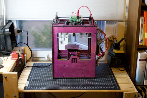
For less than that + a few evenings of assembly, I now have my own desktop 3D printer. It’s basically the Altair 8800 of 3D printers, the Makerbot “cupcake”, which is based on the open source Reprap project. It only has as a working envelope of 4″x4″x6″ so I won’t be printing anything huge, and the resolution isn’t good enough for commercial resale. However, it’s going to be trivial to print out small objects for test purposes while doing design/fabrication projects or creating structural elements for other 3D projects.

Say “Hello” to Cupcake #235:

Cupcake #235

(I stained and sealed it before assembly, it shows up as unfinished birch plywood.)

[tags]makerbot, reprap[/tags]

« Previous PageNext Page »

Powered by WordPress